Manufacturing of BESPIN parts
October was the month for manufacturing the majority of the mechanical parts for BESPIN! It was done partly in Luleå by the team in Sweden and partly in Slovenia by me, Jaka. The later was possible thanks to the mechanical workshop of a company Perovšek d. o. o. They sponsored the material, let me use their machines and helped me produce the parts.
So, how does the manufacturing of aluminium pieces with CNC machines look like? Here I will give you only a small glimpse into what I was doing the second and third week of October through a few photos that I have taken during the process.
It starts with 3D models and drawings, which was already done during the design phase. They are the prescription for the piece that we want to produce.
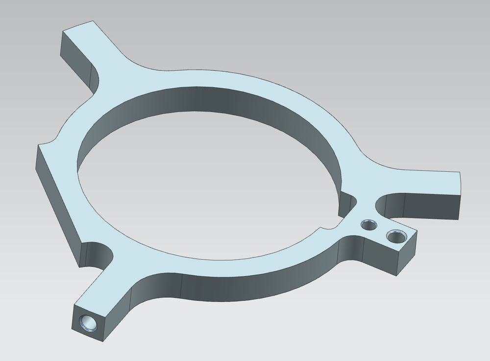
3D model of a part that reinforces and stiffens the structure:
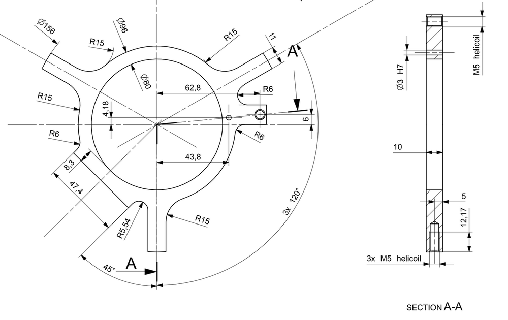
A(n outdated) drawing of a part. In mechanical drawings all the dimensions are in millimetres.
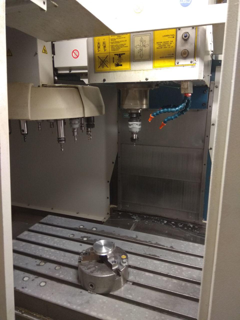
The parts were produced mostly on CNC milling machines. The machines look like this (background):

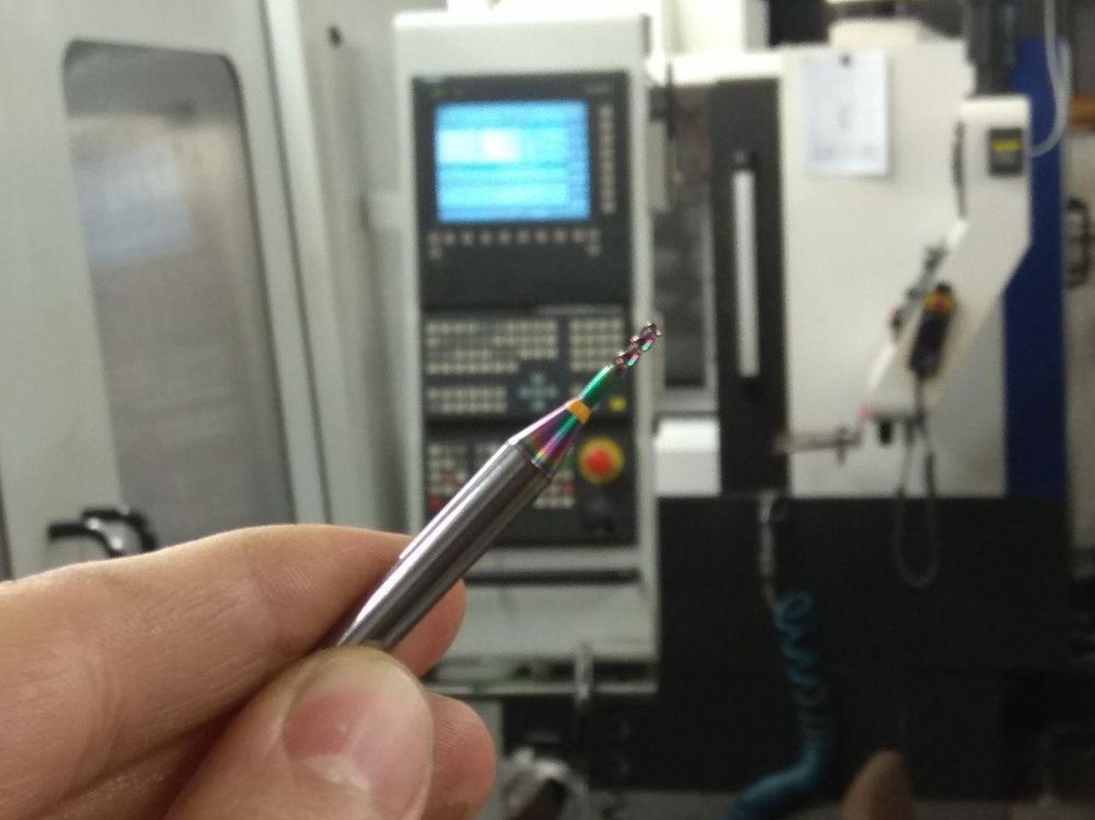
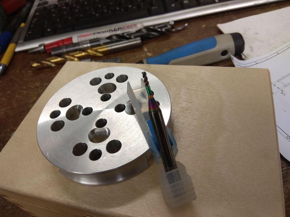
And we need tools for cutting the metal. In the upper photo I was holding a special cutter for milling aluminium with a diameter of 2 mm. Less blurry:
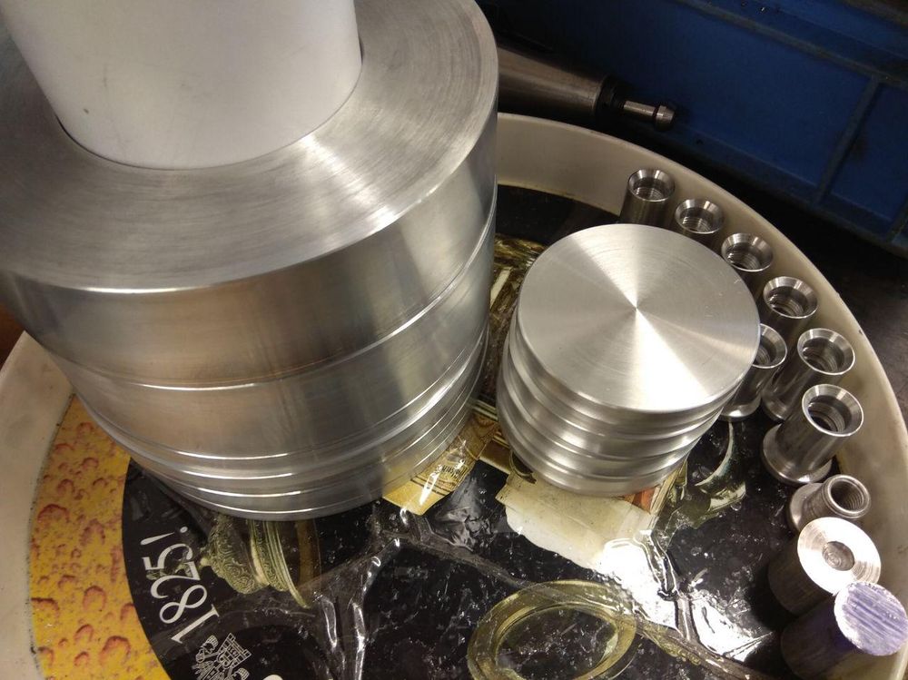
Everything starts with raw material. Or workpieces which were already partly machined on a lathe in this case.
The workpieces have to be tightly secured in the machine. Then the working coordinate system needs to be assigned to them (by touching and/or measuring the workpiece with the machine tools) for the machine to know where to work.
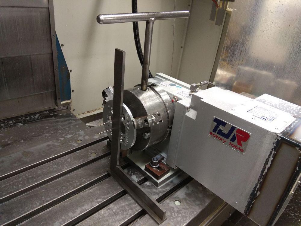
Since this particular machine has 4 axes, the workpieces were secured like this as well. (The right angle and two drills are there only for positioning while fastening the workpiece. The main part of the machining was already done on this particular workpiece.)
Besides fastening the workpiece the program has to be written as well and the tools have to be loaded into the machine and measured. Afterwards the machining can begin!
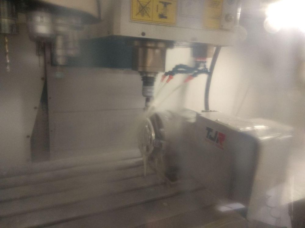
It is difficult to see the actual process clearly because there is a coolant emulsion being sprayed everywhere. But basically, the CNC machine selects the assigned cutting tool, then spins it with selected number of rounds per minute (up to 6000 in this case) and moves the tool along the Z-axis and the workpiece along the X, Y (and C for rotary table)-axis.
Often the aluminium parts are very sharp at first after machining so the have to be handled with care.
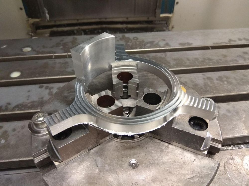
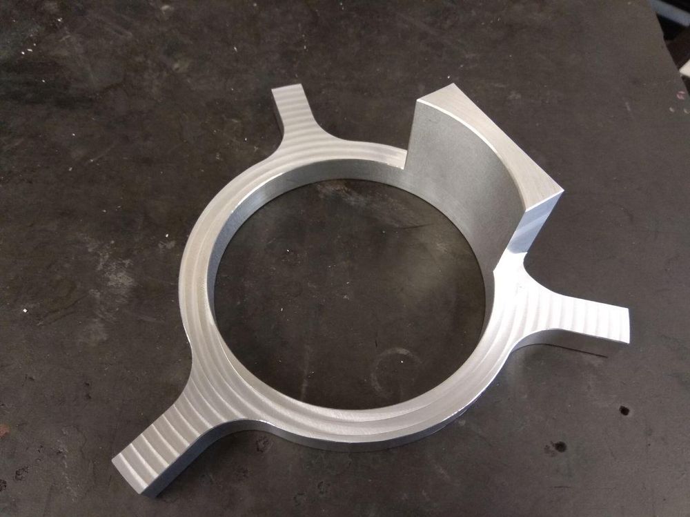
After removing the sharp edges by hand they look nicer. These are examples of partly finished parts.
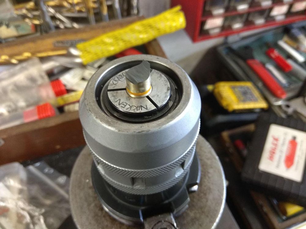
Mistakes also happen. Here you see the broken mill (worth around 100 EUR!) that I destroyed because I forgot that it would hit into metal chucks that held the workpiece from the inside when machining the groove on the inside diameter that you see in the first picture in the 3D model.
Finished parts are currently on their way to Sweden so maybe you will see photos of them in one of the next blogs.